SvensoftVideoTimeInserter 2006 - SVTI2006


Deutsch
Introduction
The Video-Time-Inserter (VTI) can be used to fade in the exact
GPS-Time (UTC)
in a
video frame. This is a free project!
It is not allowed to use it for any
commercial purposes!!!
The VTI may be assembled by everybody and it may be modified according to the users requirements.
Modifications to hardware and software have to be published!
The first version of this VTI was a VTI for EUR 10.00! The concept that is presented here can be modified and downgraded
to the EUR 10.00 version without modifying the software.
Most changes of hardware and software were made at the suggestion of Wolfgang Rothe and Eckehard Rothenberg.
Many thanks to them. Also many thanks to Niko Wünsche for doing the mechanical work.
Price: electronic stuff: about EUR 35.00, PCB: about EUR 13.00.
A shopping list for the online shop of "Reichelt Elektronik" is available (see below). The socket for the power supply can
be purchased at Segor Elektronik.
The SSM2165 used first is no longer available. I have changed the circuitry of the microphone amplifier and
it now works with a standard amplifier.
News
2006 12 31 - Hardware extension
2007 02 11 - Software update - fix of sporadic shift of the position of the line faded in the video frame
2007 02 23 - Software update - change of display of PPS-signal from "P" to a square
2007 02 24 - The bootloader is working, an extension of the hardware will be available soon.
Now everybody, who has a programming device, ist in a position to update the software via the serial bus.
2007 03 02 - Hardware extension - if two wires are soldered for the ATMega8 to the SUB-D-socket, the bootloader
can be used. This is not in full accordance with the specification of the SUB-D-bus, but no extra IC is needed.
2007 03 18 - Software extension - it is now possible to compile the software for ATMega88 and 168
2007 08 01 - Software update - after the update of 11.02.07 it occurred that
the same value for the millisecond was displayed in two different half frames. After a downgrade of the software
to the version of 11.02.07 the sporadic shift in the line position was back.
After an update of WinAVR (GCC4.12) the problem was solved.
2007 08 02 - Software update - New version of the routine for video output
2007 12 03 - Software update - revision of the set of characters, because the colon has been displayed only as one dot.
Function
The VTI is plugged between the camera and the recording device. It needs
12V (9-20V are possible). There is a protection in case the terminals are mixed up.
The VTI
is connected to a Garmin GPS18LVC GPS-receiver. This GPS-receiver guarantees the output of the exact time
at the serial bus after the PPS-signal switches from low to high.
The time is displayed in UTC!
(The image, exactly the half frame, displayed by a CCD-video-camera has been
recorded 20 ms before - for more information see the topic "determination of time".
It is possible to connect the VTI with a microphone to record comments of the observer.
As a VCR has two tracks for sound a tone synchronised with the PPS-Signal is recorded on the second track.
A green light emitting diode (LED) is blinking in the time interval of one second, triggered by PPS-signal.
If PPS-sinal is not available a red LED flashes for 1 second and is dark for one second.
If PPS-signal is available the red LED either is permanently turned on or permanently turned off.
An incidental turning on or off of the LED may occur, but this is of no relevance.
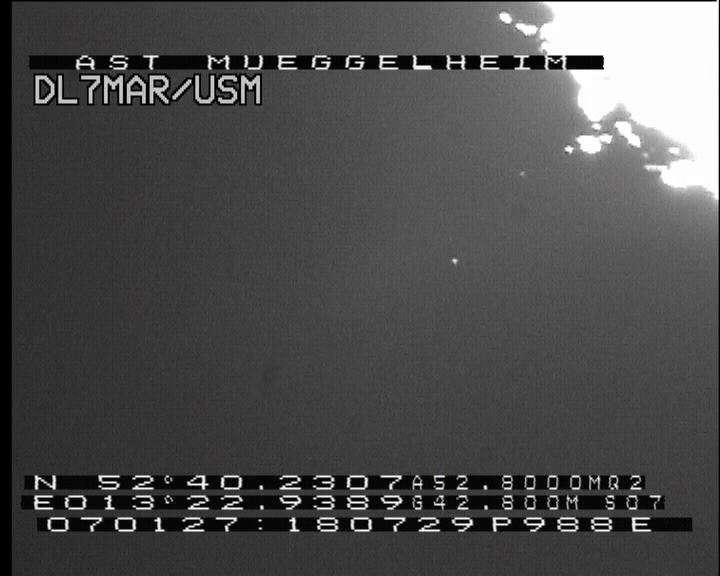
Display of time - Character size may be changed with bridge no. 5, and with R7 the vertical position of the
line could bee adjusted.
YYMMDD:HHMMSSPMMMEO
YY - Year
MM - Month
DD - Day
: - a colon is displayed if GPS-Data is valid, if not a Dash ("-") is displayed
HH - Hour
MM - Minutes
SS - Seconds
P - A Square is displayed if PPS-signal is active
MMM - Milliseconds since last PPS-signal
E - Even-Frame
O - Odd-Frame
Display of coordinates - can be turned on or off with bridge 4
N DD°MM.MMMM A1234567M Q2
Latitude
Height of GPS-antenna above NN Q-Quality: 0-no Fix
1-Normal Fix 2-Differential GPS(WAAS) 6-estimated Fix
EDDD°MM.MMMM G123456M S03
Longitude
Hight above Geoid
S-Number of satellites received
Headline - Can be turned on or off with bridge 3
In this place, for example, the name of the observatory can be displayed.
Determination of time
This page has been opened on 12.Jul.2026.at 08:50:07MEZ .
That simple it is using PHP. Using video it is a little more complicated.
A complete video frame consists of two half frames.
The first half frame contains the odd lines (1, 2, 3,...),
while the second half frame contains the even lines (2, 4, 6,...).
A half frame represents 20 ms. With CCD-cameras a complete
half frame is exposed and send to the recording device then. This means, that the half frame
displayed on the monitor has been exposed 20 ms earlier! Using the VTI
the exact time (UTC) is recorded with every half frame. The recording time
of a half frame is, in this case, the time displayed minus 20 ms.
If several half frames are added during recording the time of the beginning of the
exposure has to be calculated.
If n half frames are added the beginning of exposure is n * 20 ms earlier.
The number frames added can easily determined visually. If one looks at the single half frames
the background noise displayed changes.
It is obvious that an exact source for time is needed. In the past the only source
available was the radio station DCF77. With using the DCF-signal the following problems occurred.
- Runtime of the signal from Frankfurt/Main to the receiver - about 1 ms per 300 km
- Runtime of the signal inside the receiver - depending on the receiver from 10 ms to 80 ms!
- no worldwide availability - depending on propagation and antenna
Today GPS-receivers, which allow to read out the PPS-signal (Puls Per Second), are available
The disadvantages mentioned with DCF-time-signal do not exist with the GPS-signal.
The PPS-signal has an accuracy of 1 µs using the GPS18LVC receiver.
This is significantly smaller than the resolution of the video recorded.
Explanation of time determination in video recording - by Wolfgang Rote (in German language)
Recording of the leap second on 31.12.2008 (1MByte)
Description of software
The program of the ATMega8-microcontroller consists of the main loop and
several interrupt-routines.
- Main loop - Reading of NMEA-data of GPS-receiver
- Interrupt0 - triggered by the line synchronising impulse (German:Zeilensynchronimpuls),
fading in of the characters into the video image
- Interrupt1 - PPS, resets the timer to zero, turns the "P"-symbol on,
increases time by 1 s
- TimerCaptureInterrupt - triggered by picture synchronising impulse (German: Bildsynchronimpuls),
gets the contents of the timer (=ms), resets the line-counter to zero, pinpoints time,
turns the "P"-symbol off, sets E/O
- TimerOverflowInterrupt - a timer overflow occurs if no PPS-signal is available,
increases time by 1 s
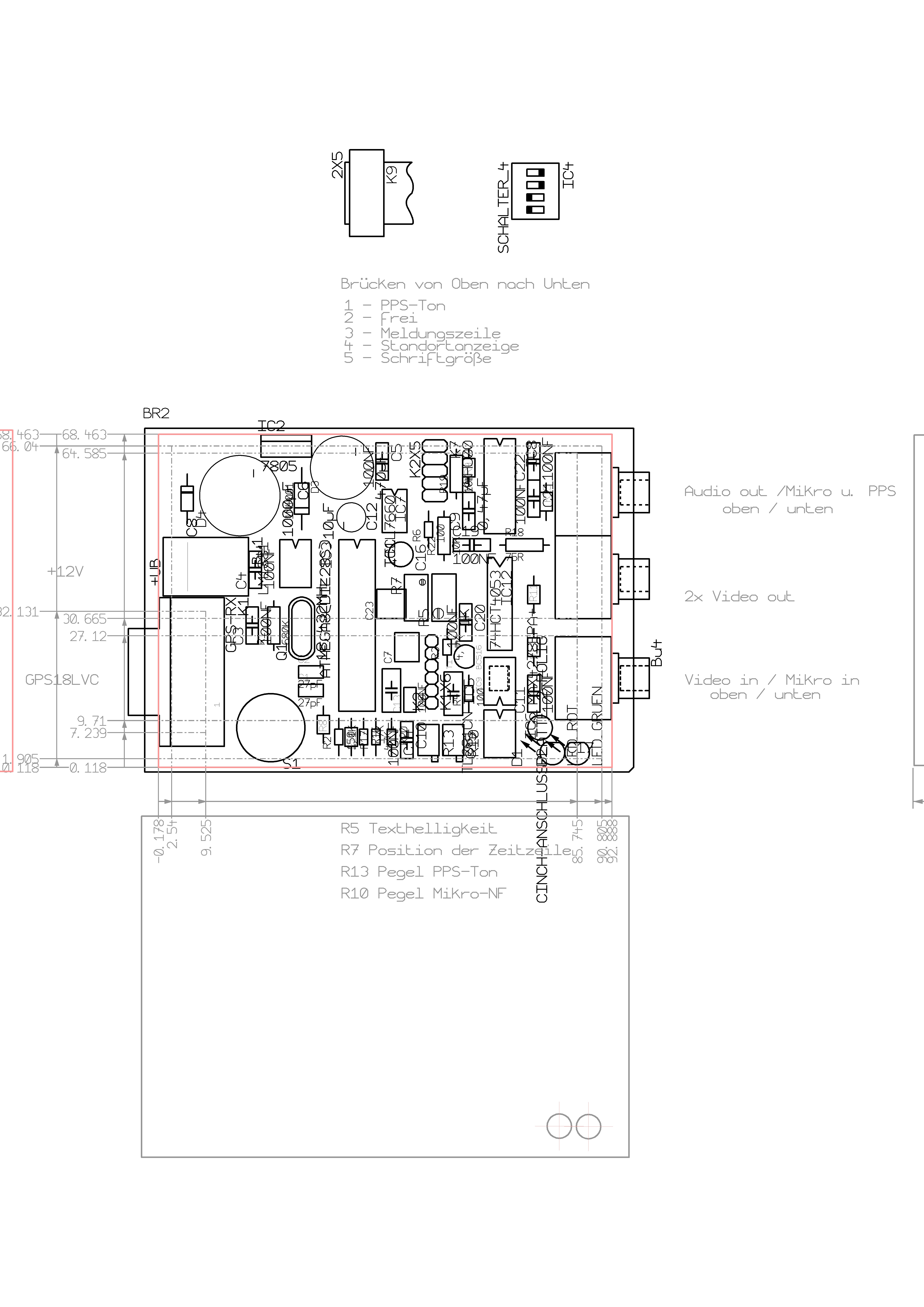
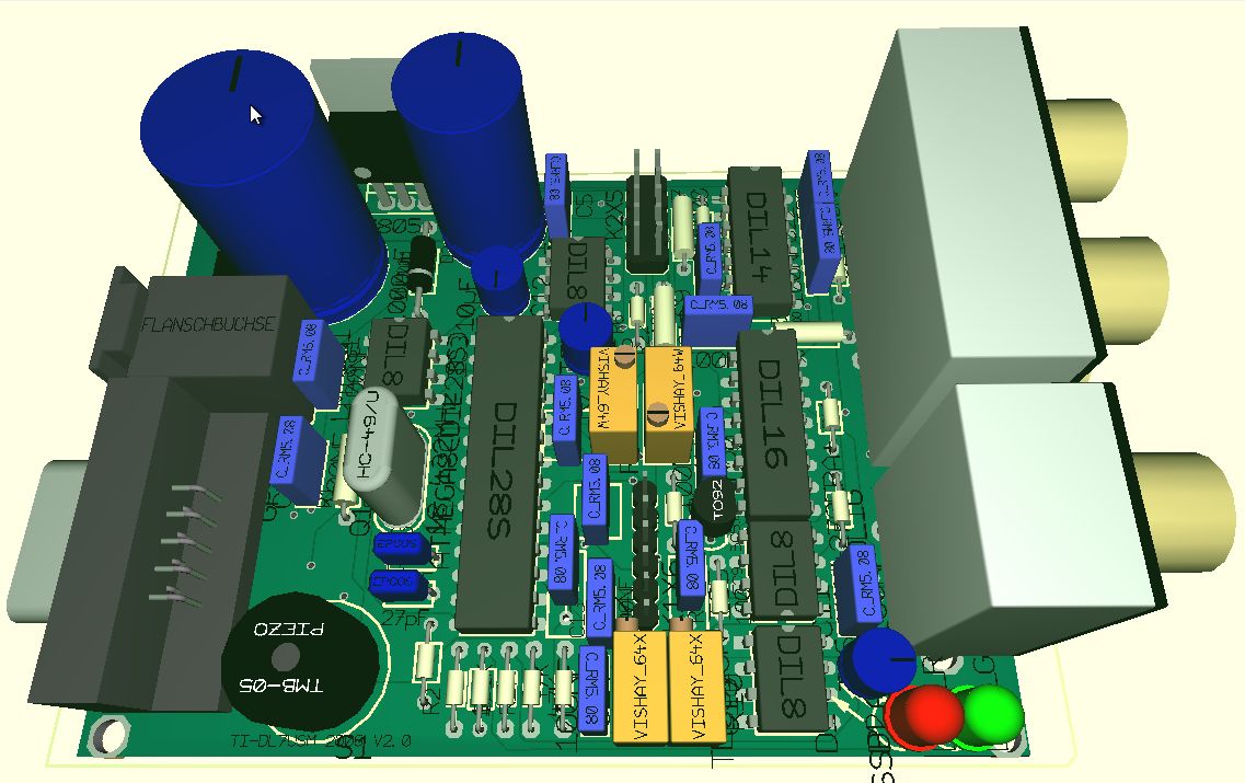
Description of hardware
The heart of the VTI is an ATMega8-microcontroller.
A LM1881 extracts the vertical and horizontal synchronising impulse as
well as the E/O-signal from the video signal.
The E/O-signal indicates wheter the frame is an even or an odd one.
These signals go directly into the ATMega8. The PPS-signal and the serial NMEA-data from the
GPS18VC go directly into the microcontroller, too.
The output at the SPI-bus of the ATMega8 is the video signal.
Therefore the multiplexer is switched. In this moment the input video signal
is turned off and the background is dark. After the multiplexer there is
an video amplifier, which makes the two video outputs available.
The PPS-signal controls a tone generator and, with the help of a gate, the green LED.
The output of the tone generator is available at a cinch socket, the level
can be adjusted with the help of an adjustable resistor (German: Potentiometer)
The microphone input is designed to connect it to standard personal computer microphone.
The signal from the microphone goes into an amplifier and the to the output socket.
The output level can be adjusted with an adjustable resistor (German: Potentiometer), too.
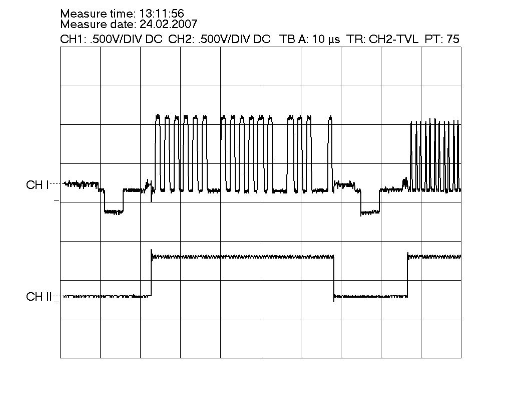
Graph of one line, where a signal is faded in, of an image shown on an oscilloscope.
Channel 1 shows the video line, channel 2 shows the switch signal for the video multiplexer.^
Download
Software for the AT-Mega8 - available soon!
wiring diagram and layout of board (Target3001) - available soon!
Manual for video time inserter
- Version of 22.02.2009,17:11UTC (in German language - English version will be available soon).
list of components
list of components as shopping list at Reichelt Elektronik.
programming and data adapter for programming the
GPS18LVC - Version of 11.08.2007,17:45UTC
Limovieguide Description of Limovie - Version of 22.02.2009,16:15UTC
Links
Target 3001 -
CAD software for designing boards
Atmel - Producer of the microcontroller used for the timeinserter
(Datasheet!!!), free environment for developing
(AVR-Studio)
Winavr -
C-compiler-environment , can be included in AVR-Studio
Garmin - Producer of the GPS-receiver used for the VTI
(Datasheet!!! and software for adjusting the GPS18LVC)
www.garydion.com - Devoloper of the routine for video output
MacAfee
Astrometrics - A free VTI, using a commercial module for fading in of video
updated
on
05 Sep 2009 18:25:48UTC by Sven
Andersson 
English version by Martina Haupt